In Vivo Pentamodal Tomographic Imaging
for Small Animals
Muhan Liu, 1,2,3 Hongbo Guo, 2,3,5 Hongbo Liu,1,2 Zeyu Zhang, 2 Chongwei Chi, 2 Hui Hui, 2 Di Dong, 2 Zhenhua hu, 2,4,6 And Jie Tian 1,2,4,7
1Engineering Research Center of Molecular and Neuro Imaging of Ministry of Education & School of
Life Science and Technology, Xidian University, Xi’an, Shaanxi 710071, China
2Key Laboratory of Molecular Imaging of Chinese Academy of Sciences, Institute of Automation,
Chinese Academy of Sciences, Beijing, 100190, China
3School of Information Sciences and Technology, Northwest University, Xi’an, 710069, China
4The State Key Laboratory of Management and Control of Complex Systems, Institute of Automation, Chinese Academy of Sciences, Beijing, 100190, China
5Contributed equally
6zhenhua.hu@ia.ac.cn
7tian@ieee.org
Abstract
Multimodality molecular imaging emerges as a powerful strategy for correlating multimodal information. We developed a pentamodal imaging system which can perform positron emission tomography, bioluminescence tomography, fluorescence molecular tomography, Cerenkov luminescence tomography and X-ray computed tomography successively. Performance of sub-systems corresponding to different modalities were characterized. In vivo multimodal imaging of an orthotopic hepatocellular carcinoma xenograft mouse model was performed, and acquired multimodal images were fused. The feasibility of pentamodal tomographic imaging system was successfully validated with the imaging application on the mouse model. The ability of integrating anatomical, metabolic, and pharmacokinetic information promises applications of multimodality molecular imaging in precise medicine.
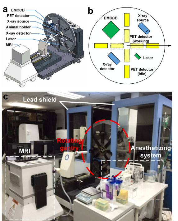
Fig. 1. System overview of our pentamodal imaging system. (a) CT, optical, and PET imaging instruments were arranged on a rotating gantry. (b)The polar coordinate system indicates the arrangement of instruments in the schematic diagram of our imaging system. Different colors are assigned for different sub-systems: yellow for PET sub-system, green for optical tomographies, and blue for CT sub-system. (c) Photograph of the overview of the system is taken before the assembling of the light shield chamber. An MRI system for verification is placed on the opposite of the rotating gantry.
More Resources
In Vivo Pentamodal Tomographic Imaging for Small Animals
In Vivo Pentamodal Tomographic Imaging for Small Animals Muhan Liu, 1,2,3 Hongbo Guo, 2,3,5 Hongbo Liu,1,2 Zeyu Zhang, 2 Chongwei Chi, 2 Hui Hui, 2
Article: Tumor-targeted Responsive Nanoparticle-Based System for Magnetic Resonance Imaging Therapy
Tumor-Targeted Responsive Nanoparticle-Based Systems for Magnetic Resonance Imaging and Therapy Ronak Savla & Olga B. Garbuzenko & Suzie Chen & Lorna Rodriguez-Rodriguez & Tamara Minko
Article Review: A Surrogate Marker for Very Early-Stage Tau Pathology is Detectable by Molecular Magnetic Resonance Imaging
Article Review: A Surrogate Marker for Very Early-Stage Tau Pathology is Detectable by Molecular Magnetic Resonance Imaging System Used:M-Series Compact MRI Download PDF Here There
(October 12, 2021) Webinar: Clinical Field MRI As A Measurement Instrument for 3D Printing and Bioprinting
(October 12, 2021) Webinar: Clinical Field MRI As A Measurement Instrument for 3D Printing and Bioprinting Overview: Watch our webinar where Professor Marc-Andre Fortin presented
(May 6, 2021) Precision Oncology: Combining Orthotopic-PDX Models and MRI, Moving Research Forward, and Improve Clinical Outcomes
(May 6, 2021) Precision Oncology: Combining Orthotopic-PDX Models and MRI, Moving Research Forward, and Improve Clinical Outcomes Overview: Certis Oncology Solutions is a precision oncology
(May 5, 2021) Webinar – Modality Review: The Basics of Photoacoustic and Fluorescence Tomography
(May 5, 2021) Webinar # 1 – Modality Review: The Basics of Photoacoustic and Fluorescence Tomography Overview: In this webinar, we introduced the fundamentals of
( April 13, 2021) WEBINAR: Multimodal Optical and Morphological Imaging in Cancer and Drug Research
(April 13, 2021) WEBINAR: Multimodal Optical and Morphological Imaging in Cancer and Drug Research Overview: Multimodal imaging has evolved as a key technology in preclinical
(March 9, 2021) WEBINAR: Low-Field MRI for Optical/MRI Studies of Optical Clearing In Vivo
(March 9, 2021) WEBINAR: Low-Field MRI for Optical/MRI Studies of Optical Clearing In Vivo Overview: Dr. Bogdanov discussed how multimodality registration of optical and magnetic
Certis Oncology Intelligence: The Science of Certainty
Certis Oncology Intelligence: About Certis Established in 2016, Certis Oncology Solutions is a precision oncology and translational science company. It works directly with cancer patients
(February 16, 2021) WEBINAR: Combined PET/MR imaging: Technology and Applications
(February 16, 2021) WEBINAR: Combined PET/MR imaging: Technology and Applications Overview: Dr. Lee discussed how simultaneous PET and MR data acquisition using a fully integrated